MUR Blog - Aerodynamics: What do we really do?
Since the start of this year, we’ve been striving to build upon what was already a great design that the 2016 Aerodynamics (AE) team left behind for us. Not only do we aim to perfect the ideas and concepts introduced in 2016 but to also introduce some of our own ideas to design and implement an even better aerodynamic package for our 2017 combustion car. This article will briefly introduce the overall purpose and role of the aerodynamics team, our design process and what changes have been made from the previous year.
In 2016, the AE team was led by James Hancock along with Kevin Kearney, Catherine Glassenbury and Ethan Lo. The 2017 team this year consists of only two members: myself (Andrew) and Harry Travers.
The primary task of the aerodynamics team is to design an aerodynamic package to enhance the overall performance of the racecar. To achieve this, not only must the package be designed to generate high amounts of downforce, but also maintain vehicle stability under all foreseeable racetrack driving conditions. Additionally, the aerodynamics team is also responsible for ensuring components such as radiators and brakes are sufficiently cooled.
For design optimisation, a wide range of software tools is used to help us perfect our aerodynamic package. The two major tools we use are Fusion 360 by Autodesk for creating computer-aided design (CAD) models, and ANSYS Fluent for running computational fluid dynamics (CFD) simulations. Autodesk and ANSYS are both valued sponsors of MUR.
Simulations are a big part of our design process. Since we lack a physical wind tunnel, the team relies on fluid flow simulations to determine the performance of proposed designs, and because of this, emphasis on accuracy is placed. The simulation process typically consists of the following steps:
- Importing geometry from CAD
- Setting up the fluid domain (i.e. virtual wind tunnel)
- Meshing the relevant components
- Setting up boundary conditions
- And finally, running the simulation until an acceptable convergence is reached.
Once we lock in on a design, manufacturing will begin. The performance of the design is heavily affected by the quality of manufacture. Some of the tasks the team takes on at this stage is procurement of materials (such as carbon fibre, aluminium, hex core, Kevlar etc.), researching different ways of manufacturing components, and of course manufacturing itself which typically takes around 2-3 months depending on complexity.
So, what have we been up to so far?
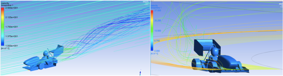
Straight (left) vs. Corner (right) simulations
One of the major upgrades the aerodynamics team have undertaken this year are the changes made to our ANSYS simulations. Due to CFD simulations being a critical part of the aerodynamic design process, a significant amount of time and effort was invested by the 2017 team to revamp the CFD simulation setup used in previous years.
Meshing: In previous years, MUR’s AE teams have used tetrahedral meshes across the entire wind tunnel domain. Tetrahedrals were the preferred choice of mesh type because they are much more tolerant to geometry in general. This is a major factor since the full car CAD model used for simulations consists of a large variety of geometry properties such as sharp angles, small faces and curved faces. Having a good mesh will not only enable simulations to run smoothly and allow a convergence of solutions, but helps improve the accuracy of simulation results. However, tetrahedral mesh types are considered to be unstructured mesh cell types and are inefficient as they increase simulation processing time. With limited processing resources and time, it is paramount to decrease processing time while maintaining accuracy of results.
As such, a new wind tunnel mesh was developed and used this year. The image below shows the difference between the 2016 and 2017 meshes.
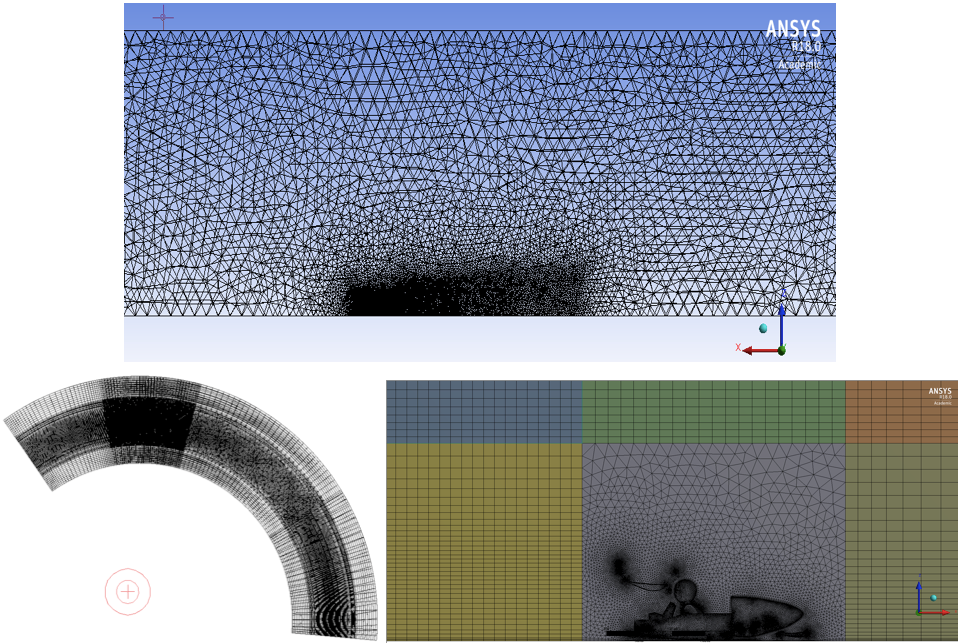
2016 Tetrahedral mesh (above) vs. 2017 Tet-quad hybrid mesh for curved and straight simulations (below)
The 2017 mesh setup uses a hybrid of tetrahedral cells as well as swept cells to create structured quad cells across the entire domain. This setup allows us to take advantage of the benefits of both cell types: tetrahedral cells still allow better meshing tolerance on the car geometry, while the significantly more efficient quad cells provide the benefit of decreased processing time while increasing accuracy of the rest of the wind tunnel domain which does not consist of any geometry. By using this new meshing method, the productivity of the aerodynamics team is raised by both saving time and improving the quality of results.
Cornering Wind Tunnel: Another new addition to our team’s toolkit. With our aerodynamic package designed specifically for cornering conditions, it only makes sense that these conditions be replicated as accurately as possible in our simulations.
Previously, cornering conditions have been simulated by placing the car in a straight wind tunnel at an angle. While this does replicate the condition of oncoming relative flow at an angle, it does not fully capture the primary characteristics of a corner – specifically, the ‘curved’ path the oncoming flow takes relative to the race car. By building a circular wind tunnel, our team can generate a curved flow as well as a rotating ground to capture ground effects around a corner. Additionally, the cornering wind tunnel also allows the team to simulate corners at different radii and velocities easily, as well as what happens to flow during corner entry and exits by positioning the race car differently around the wind tunnel.
Not only does this improve the modelling accuracy of our simulations, it also allows the team to have greater insight on the flow properties that occur during a corner. We can then in turn make better informed decisions during our design phase.
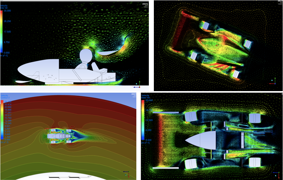
2016 Showcasing flow at an angle (top two) vs. 2017 Cornering wind tunnel results (bottom two)
With these new updates to the 2017 AE team, we hope to be able to streamline and increase the efficiency of our simulation process and further improve the aerodynamics package from 2016 as well as lay out a foundation for the 2018 team to work upon. With the ever-evolving competitive design environment in FSAE, it is important for the team to adapt and improve upon every preceding year. Therefore, it is paramount for knowledge transfer to take place on a year to year basis via our MUR Junior Program which doesn’t only promote knowledge retention within the team, but also provides our juniors with opportunities to continue building upon this ever-increasing foundation of knowledge.
Want to hear more from us? Sign up here and never miss a post! No spam, promise.
About the Author:
Andrew Chak
Lead Aerodynamics Engineer, 2017
Junior Aerodynamics Engineer, 2016