MUR Blog - Ansys CFD during Coronavirus in 2020
The design of an effective aerodynamics package is never an easy task but in 2020 it was made significantly harder. Coronavirus caused a university shutdown, Melbourne lockdown, and Aero team members to have no face-to-face contact since March. With the help of Ansys Fluent and other software’s, Melbourne University Racing was able to develop an aerodynamics package from home.
The Melbourne University Racing aerodynamics team uses the Ansys Fluent CFD package to optimise the design of the front wing, rear wing, undertray, nosecone and side aero. Ansys Fluent allows us to simulate the car in various straight-line and cornering conditions, as well as accompanying dynamic conditions including dive, squat, and roll. The three critical values that are measured are the downforce, drag and mass-flow rate of radiators. The goal of the aerodynamics team is to create a design that features maximum downforce, minimum drag and adequate airflow to the radiators for effective cooling.
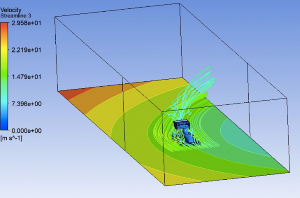
Figure 1: Cornering Simulation
University of Melbourne’s first semester started on the 2nd of March and the MUR team was excited for a new year after winning a podium finish in one of the dynamic events of last year’s competition. At that time coronavirus was not a serious threat and we were still had in-person classes and tutorials. The MUR aerodynamics team had two physical desktops loaded with Ansys Fluent which we had used the last few years to perform CFD. At the beginning of March, we shared the two desktops between the four of us while we conducted mesh convergence and inflation layer analysis. If any of us had a problem we would huddle around the desktop until we had solved the issue.
Cue to three weeks later when the University shut its campus, states were shutting their borders and the whole of Australia was going into lockdown. The MUR team at the time believed that the December Formula SAE-A competition was still a possibility, so the aerodynamics team kept working. However, we had lost the physical desktops and any face-to-face contact. We solved this problem through a combination of virtual machines, Fusion 360, google drive, zoom meetings and Ansys Fluent.
The University of Melbourne was kind enough to provide us with virtual machines that allowed us to remote connect to and control a “desktop” with better specifications than what we were using. Our straight-line simulation times dropped from 8 hours to 5 hours. These virtual machines operated in a “pool” which allowed everyone on the aero team to have their own “desktop”. These virtual machines increased the turnover of our simulations and iteration of designs. This however created another problem. How to keep each part of the car up to date with the current designs of the multiple aerodynamic engineers. This was solved by a careful filing and ordering system implemented within the cloud-based Fusion 360 software. It allowed everyone to know which parts were current and able to be used for simulations.
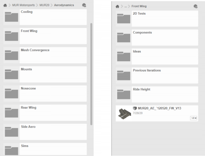
Figure 2: Fusion 360 Filing System
As we had new members to the aerodynamics team, we had to teach them how to use Ansys Fluent. Wilson Zheng, who was a current and previous aerodynamics member, posted Ansys “tutorial” videos on google drive so that if we forgot a step we could go back and remember it. This also ensured that everyone was following the same procedure so that each simulation was the same for every engineer. Every simulation was recorded on a joint document showing important data and which part version was used. We also keep up to date mesh and inflation layer sizing files in a google drive folder so that everyone used the same mesh settings. For anyone having serious problems, we would use the screen share function of Zoom and help each other through the process.
However, the most important piece of software was the CFD solver. We used Ansys Fluent for all our simulations with great results. Though Ansys Fluent was not designed for shared collaboration there are several features that helped our team during 2020. Most notably is the ability to import and export mesh sizing and inflation layer sizing files. Being able to keep up to date and consistent mesh sizing’s meant our simulations stayed consistent. Later in the year, we discovered how to create scripts to run our entire meshing process by copying and pasting code from a notepad document. This further improved our ability to maintain consistent simulations.
As the year went on it become apparent that the Formula SAE-A competition was not going to run an in-person event and nor would the university allow on-campus manufacture. This was disheartening for the entire team and especially so for those whose subsystems were part of their capstone projects. The aerodynamics team shifted focus from design to ensure that next year’s team would hit the ground running with a new cornering wind tunnel and an extensive mesh convergence and inflation layer analysis.
For example, each aerodynamic component had an individual mesh convergence and inflation layer analysis conducted. An inflation layer analysis for the front wing was conducted to determine a first layer height that accurately captured the boundary layer and the interaction of the fluid at the wall. A range of heights was tested and the CLA plotted, as shown in Figure 3. From this plot, it was determined that a first layer height of 5 mm would be appropriate given the convergence of CLA at this value and the low percentage of cells below a y+ value of 30. A key requirement for accurate modeling is to reduce the number of cells that fall within the buffer region (5 < y+ < 30) so that the near-wall effects of the fluid are captured better. Plotting against time as shown in Figure 4 also revealed that a first-layer thickness of 5 mm produces a shorter run time than smaller values, which reduces the computational costs of the simulation.
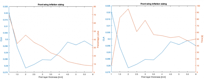
Figure 3: Inflation Layer Analysis Figure 4: Inflation Layer Run Time
A new cornering wind tunnel was developed by Wilson Zheng that heavily reduced simulation times. Though the wind tunnel looked like a straight-line tunnel it worked by specifying inlet and outlets at opposing corners to create a combined turning motion of airflow. It simulated the curved nature of air more accurately than simulated yawed flow. A Lapsim run by the integration team revealed the cornering radius to be 12.5m. The vehicle was simulated turning left, and to model the vehicle during cornering, a -2 degree slip angle and a slight roll of 1 degree were applied to the model, as determined by the steering and suspension parameters respectively. Based on steering parameters, slip angles of 8.8 degrees and 9.8 degrees were also applied to the front left and right wheels respectively to reflect their position while turning. The ground was set to rotate at 1.2 rad/sec and the fluid domain was also specified to be rotating about the cornering radius of 12.5m at 1.2 rad/sec with a velocity reference value of 15m/s. Below is a comparison between our 2020 and 2019 cornering wind tunnel setups.
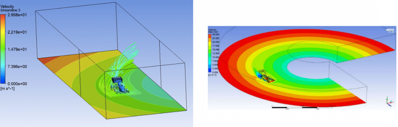
Figure 5: 2020 Cornering Wind Tunnel Figure 6: 2019 Cornering Wind Tunnel
As the aerodynamics lead for 2021, we would like to thank the 2019/2020 team for the strong foundation laid by them. The design and optimisation of our high-performance aerodynamics package would not be possible without assistance from our partners at Ansys.
About the Author:

Griffan Wallish
Aerodynamics Lead, 2021