MUR Blog - Getting Started with Stereo Vision
With the resources made available to the team this year, this article hopes to illustrate the team's goals in being able to pinpoint image rectification & stereo triangulation for our driverless car.
With our current resources, we have started with using a pair of GoPro Hero 5 sessions for our bench testing needs. By using them to capture still images of calibration targets.
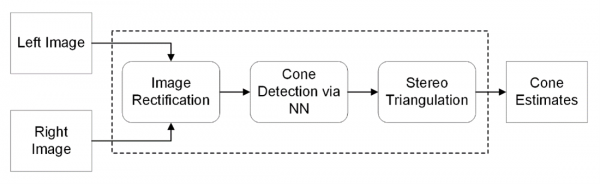
Proposed stereo vision pipeline
As seen in our proposed stereo vision pipeline above, we plan to follow quite a standard stereo vision pipeline for 3D reconstruction/pose estimation. However, for our use case of cone localisation and detection, certain assumptions and simplifications can be made.
Image Rectification
Before anything can be done beforehand, the raw images have to be processed through a series of rectifications and calibration steps.
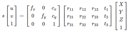
First up, is the calibration and undistortion step. In which the intrinsic and extrinsic parameters are found. In which real-world coordinates (X,Y,Z) are projected into the pixel coordinates (u,v).
As epipolar geometry uses some assumptions based on a pinhole camera model, the raw images from most modern-day cameras would still require some distortion correction due to defects within the camera lenses, which occur in both the radial and tangential directions.
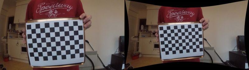
As seen above the GoPros we were using for testing, uses a fish-eyed lens often seen in sports/action point of view cameras as they are often marketed as more “immersive”. However, for our use case, such a fish-eyed effect is considered a negative and thus was removed by calibration. As seen with a test image above.
So far all that has been done was on a per camera basis, the next step stereo rectification is based on the general stereo setup in which the image planes of the two cameras within the stereo setup are not on the same plane. Rectification conducted to simplify calculations down the pipeline as when the image plane of two cameras coincides, epipolar geometry simplifies down to a simple geometry problem of similar triangles. We, however, can further simplify things by having the two cameras be mounted on the same plane from the start, which allows us to skip this step.
Stereo Triangulation
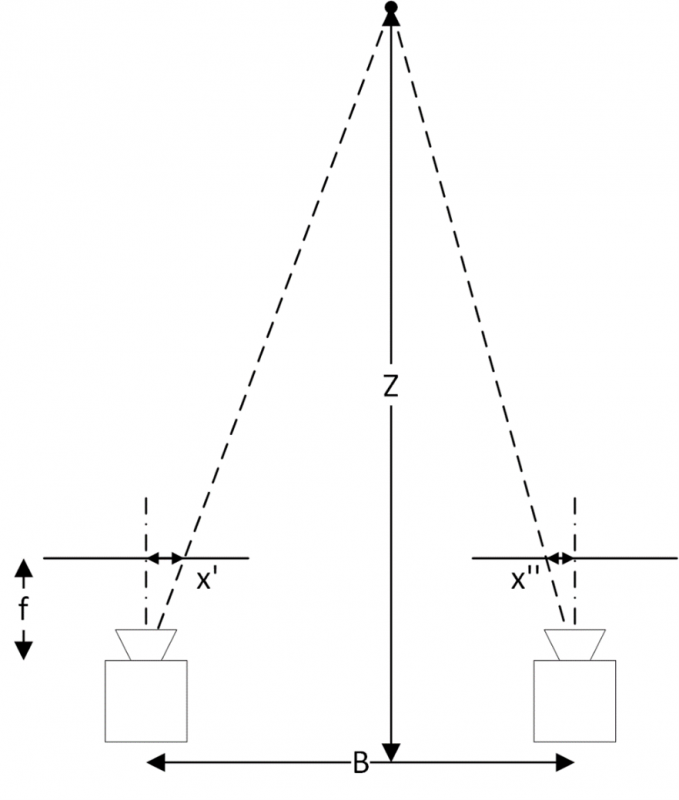
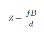
A starting point of stereo triangulation is a simple depth from disparity calculation. As mentioned earlier, epipolar geometry simplifies a problem of similar triangles, as seen in the diagram above. Where, Z is real-world depth of the target object, B is the real world baseline (distance between the two camera centers), f is the focal length of the cameras in pixel units, and x′ and x′′ are pixel location of the target object projected in the left and right image. Thus it is simple to see that depth is simply inversely related to the disparity of the object (d=x′−x′′) or the difference in horizontal pixel coordinates in the left and right image,
This is the fundamental calculation used in disparity mapping a related concept to stereo vision, in which a depth map is produced from a pair of stereo images. For our use case however, we are not interested in the depth map of the environment but rather only the cones for tract boundary detection. As seen from the image pipeline from the start cone position will be fed into from a detector neural net, and thus would significantly cut down the required processing compared to a disparity map.
About the Author:
 Andrew Huang
Spatial & Perception Engineer, 2020