MUR Design Newsletter 2017
After a four-month design phase, we are currently knee-deep into manufacturing. Below, each subteam describes and explains their design decisions behind both our internal combustion vehicle and electric vehicle both expected to be at the FSAE-A 2017 and 2018 competitions respectively.
Internal Combustion
Integration
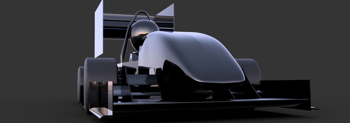
Sneaky Peeky
Building on the KTM platform change of last year, this year’s team goals for our combustion car are to ensure a reliable and competitive car is brought to competition in December. To realise these goals, the decision was made to step down from a turbocharged engine to a naturally aspirated electronically fuel injected KTM 525 EX-C. To allow novice drivers to competitively race the car at competition, there has been a greater ergonomic focus on design of the monocoque chassis. The aerodynamic package has been optimised for constant downforce and to reduce COP migration across a range of wind and driving conditions, while the five-spring suspension setup allows for a highly tuneable system with packaging simplicity.
With this design, we hope to find a better balance between reliability, simplicity in manufacture/tuning while still maintaining a high-performance car.
Chassis

Male Chassis Mould Being Hand-Shaped to Size
The chassis team is responsible for the design, optimisation and manufacture of the car’s main structure. The chassis’ overarching aim is to integrate all the vehicle's subsystems with a lightweight, yet sufficiently rigid structure to maximise vehicle performance.
This year has had a heavy focus on shaping the design around the driver, not only protect the driver in the incident of a crash, but to also allow for a robust and efficient driver interface to maximise driver performance.
Engine
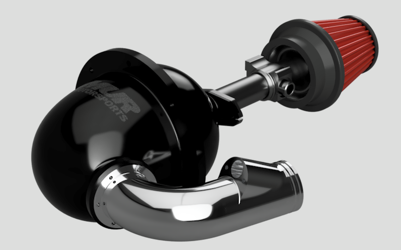
Engine Intake System
As mentioned, we are using a KTM 525 EX-C engine this year which we are converting from a carburetted fuel system to an electronically fuel injected system. The internals of the engine will remain stock and focus will be placed on development of the EFI system to suit this new engine to provide a good platform for future years to customise and improve on.
Besides that, we are using a dual radiator system. The radiators are single pass and operate in parallel to each other with the aid of an electric water pump.
The intake is a combination of aluminium tube for the runners and a 3D printed plenum to combine strength against vibrations and freedom of design/ease of manufacture for the plenum.
Steering and Suspension

Rear Activation Design/Subsystem
The goal of the steering and suspension subteam is to create a system tailor-made for amateur drivers, that regulates and controls tyre contact to maximize cornering performance.
This year we’ve placed a greater focus on serviceability. Transitioning from a six damper system to a five damper system, we've simplified our system for greater ease of tuning, whilst still exploiting the powerful mode separation of a heave spring design that allows us to optimize our aerodynamic performance without compromising our low speed cornering capabilities.
Along with a revamped steering system and a more reliable upright design, we expect our subsystem to successfully meet the team’s top-level design goals of a reliable, high performing F-SAE vehicle suitable for amateur drivers.
Brakes and Drivetrain
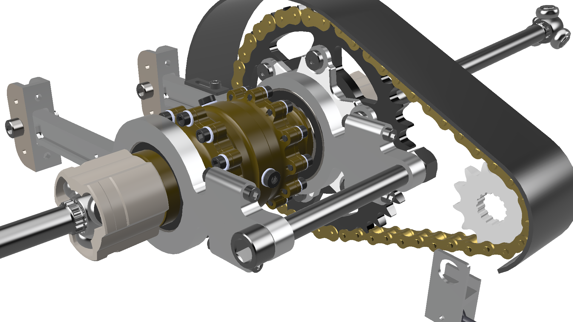
2017 Driveline Setup with Adjustable Differential Mount to Accommodate Chain and FDR Adjustment
The 2017 design builds on the 2016 car by improving reliability and functionality on an already high performance design. The 2017 car features differential mounts that can accommodate either a spool or Drexler clutch plate limited-slip differential, and facilitates adjustable final drive ratios for tuning on what is a relatively untested engine platform.
A floor mounted pedal box allows for a more comfortable driver foot elevation, simultaneously lowering centre of gravity and reducing component complexity. Fast and reliable gear shifts can be made with the push/pull cable shifting mechanism whilst floating disc brakes mean the driver can confidently apply maximum braking force in a controlled and predictable manner.
Aerodynamics

CFD Simulation Provides Insightful Details Regarding Airflow, Allowing the Team to Make Informed Design Decisions
With the purpose of boosting performance, the MUR AE team designs and builds a full carbon fibre aerodynamics package to maximise downforce and manage dynamic stability.
With an increased wheelbase in 2017, the AE team is permitted to take advantage of the extra area, opening up room for additional features such as a five-diffuser undertray, allowing for additional downforce. 2017 will also see new changes to the wings. Footplates in the front wing will help improve flow redirection using vortices while larger rear wing endplates will enhance pressure trapping. With the new development of a circular cornering CFD wind tunnel, we have gained new insight in designing for cornering, giving the team an improved model of track dynamic conditions.
Electric Vehicle
Integration
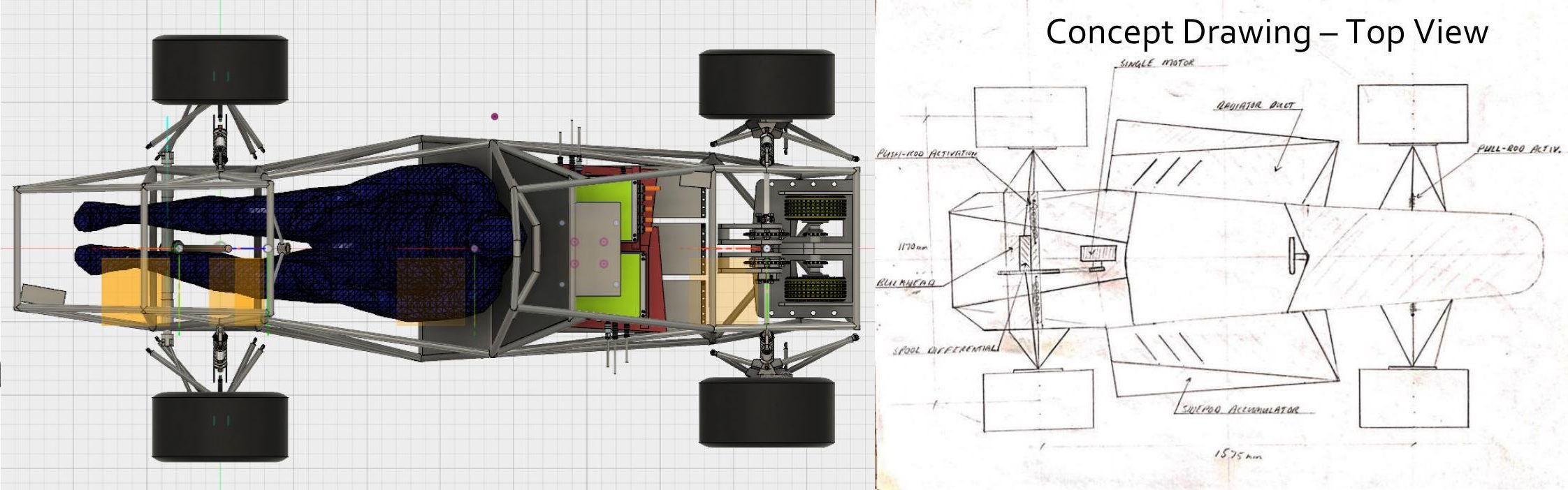
Initial (L) and Current (R) Concept
MUR changed the top-level concept of the EV in two distinct ways as may be viewed visually in the images above.
The first change is that we are moving to a single drive vehicle after an in-depth analysis was carried out using MUR's new electric lap simulation program which showed that the point difference in implementing the single motor was insignificant while allowing for increased reliability. The second change is that the side pods will now accommodate the accumulator. This change will lower the center of mass and allow for a shorter wheelbase which will permit the car to take better racing lines.
Chassis
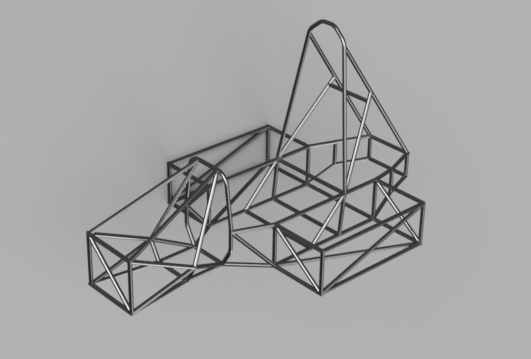
Preliminary Chassis Rendering
A mild steel space frame is used for the EV chassis due to the high stiffness to weight ratio and ease of manufacture, on top of it being a safe choice for our first EV. As for main structure, the current mass is around 28 kg with the torsional stiffness being above 1400 Nm/deg. Since we are using A123 battery cells – which is a safe option but makes for a heavy space-consuming battery pack – we’ve decided to use two battery containers and place them on either side of chassis instead of at its rear to reduce the overall length of the car and allow for proper mass distribution. We are using a rear bulkhead to mount the drivetrain and part of rear suspension on the chassis.
For the driver cell, the driver seat is made of expanding foam, which is low-cost and easy to manufacture; the cockpit space is designed to maximise driver comfort. The floor panel will be made of carbon fibre to add some stiffness to the car while keeping its overall mass low.
Steering and Suspension

Ohlins F-SAE Damper
As this is MUR’s first EV, our design goal is to build a reliable and highly adjustable system. Building upon experiences from previous combustion cars, an inboard suspension system is used at the front and rear of the vehicle. Shims, adjustable tabs and inserts are used to provide tuning ability to the car. Uprights and stubs are modified to increase the factor of safety. The system will be thoroughly tested and tuned (hopefully close) to perfection next year.
Brakes, Drivetrain and Thermal Systems
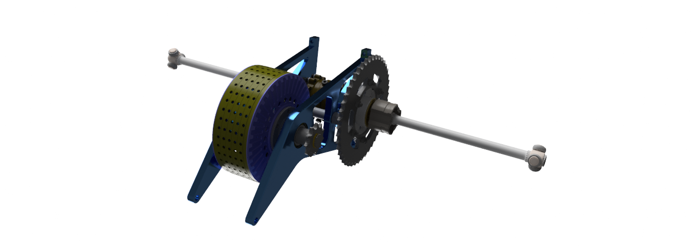
Drivetrain Assembly
BDT is responsible for delivering power to the wheels of the EV. We also act as the driver interface for vehicle acceleration and deceleration, and are responsible for monitoring the vehicle temperature.
We have custom designed a drivetrain system which is optimized for a single electric motor driven vehicle. The pedal box system has been engineered to deliver accurate control to the driver over the vehicle speed with a braking system focused on fast and efficient deceleration to minimize lap times. Our cooling system incorporates liquid and air cooling technologies to ensure that our motor, inverter and accumulator can operate optimally even in extreme heat.
Electric Powertrain
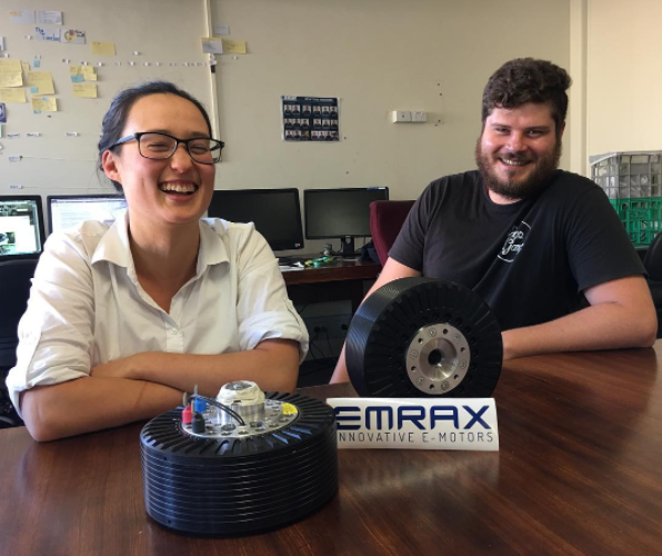
2/3 EPT ft. Emrax 208 Motors
EPT have selected a permanent magnet synchronous AC motor along with an inverter (to convert our main battery voltage into the three-phase AC required) due to this system’s superior combination of power to weight ratio, efficiency, availability and ability to implement regenerative braking.
Since then we’ve been working to model this distinctly non-linear system, which has included characterising the control processes that are already programmed into the inverter. The construction of an oppositional dynamometer (wherein two motors are attached to the same shaft, but one is run as a motor, the other as a generator) is also underway, which will allow us to precisely control the load; this will facilitate system identification and permit us to simulate disturbances to test our control algorithm all while being energy efficient.
Accumulator
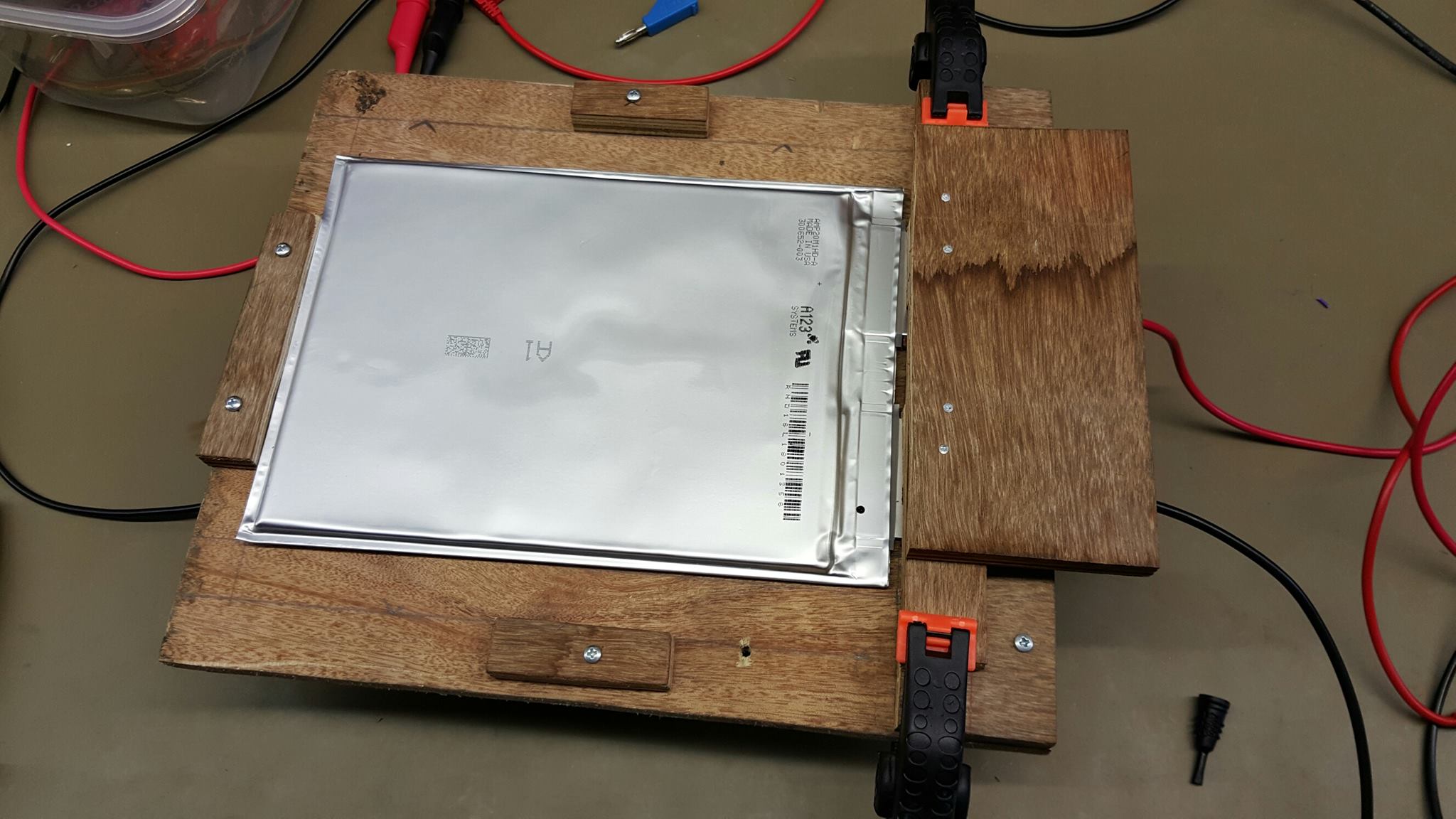
A123 Cell Battery Under Charging State Condition
Our accumulator consists of 96 A123 AMP20HD-a cells, divided into eight segments, enclosed in two containers. These cells were selected primarily based on chemistry safety and energy density, ensuring high performance while always keeping safety as top priority. The segments can be easily connected and detached for maintenance while able to maintain being securely locked during vehicle use, thanks to Amphenol's SurLok technology. Internally, each segment has a cooling plate and fins to ensure optimal operating temperature for the overall system.
Battery Management System
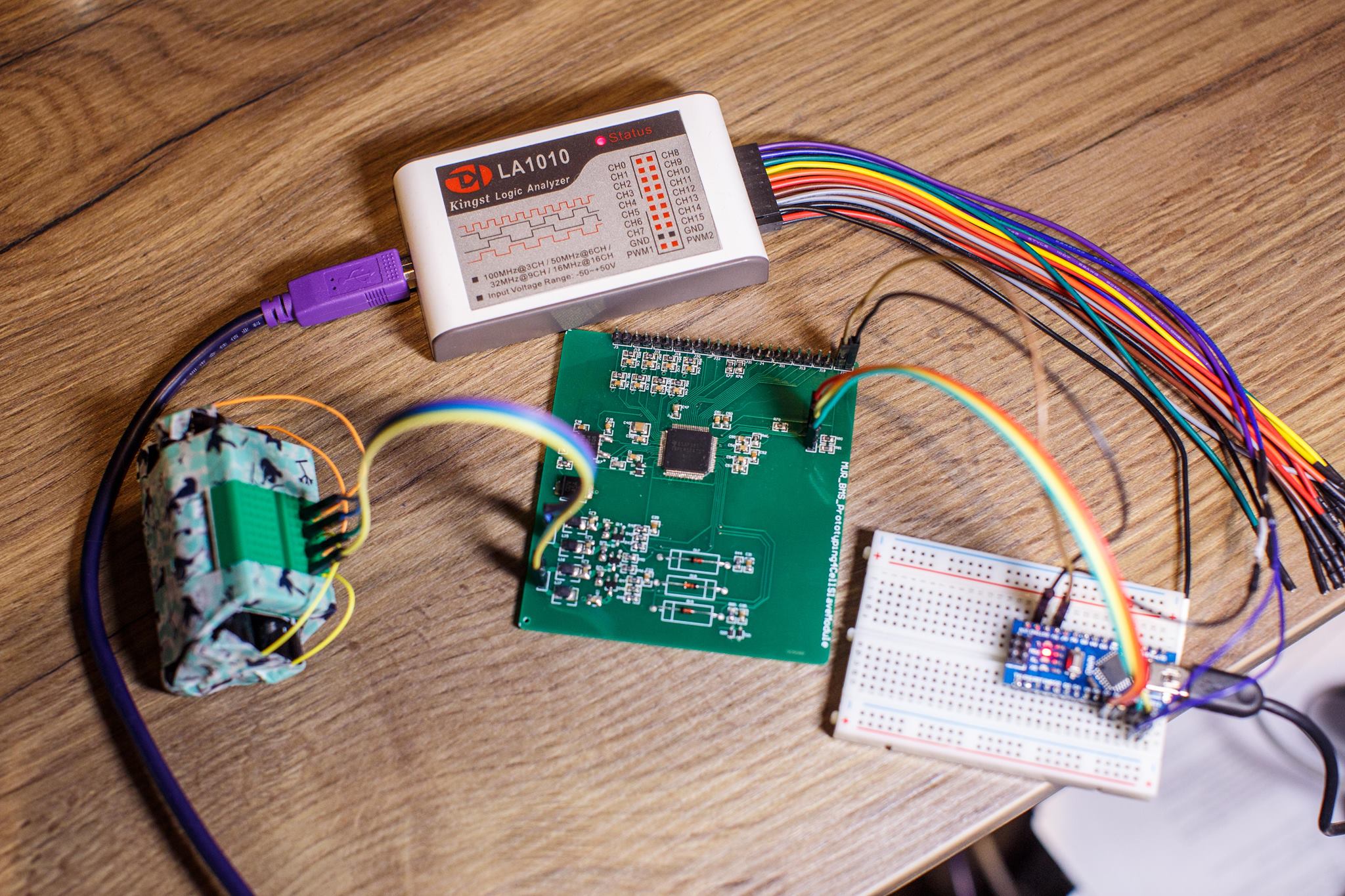
Debugging a Prototype Voltage Monitoring Module
BMS is responsible for developing an effective and reliable BMS for the EV. Each accumulator container is monitored by a BMS whenever the EPT is active or the accumulator is connected to a charger. This year’s BMS is designed around two ASICs from Texas Instrument which are controlled by an ARM processor to achieve both cell monitoring and balancing.
Low Voltage
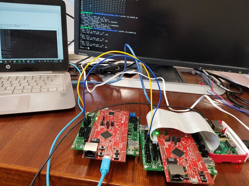
Data Acquisition System Being Debugged
The LV system consists of the power supply, safety system, data acquisition system, and some other features. The safety system controls the coils of the accumulator isolation relays. Most of the features have been tested and provide satisfactory results. The data acquisition system deals with sensor measurements, Controller Area Network and data logging – testing is still in progress. Some other available features include Tractive System Active Light, ready to drive sound and brake light. The LV system also interacts with other systems by trading signals.