MUR Blog - Full Stack Integration
Both the perception/spatial and control sub-team has been busy at work, trying to integrate all the different components which we have been working on throughout 2020.
Integration Testing
This includes:
- Perception Components
- LiDAR Pipeline
- Stereo Camera Pipeline
- Localisation and Mapping
- GPS/IMU Pipeline
- SLAM
- Control Components
- Path Planner
- Path Follower
ROS Distributed Setup
One of the challenges faced during our testing was the lack of computational power to run all the components together in real-time. To elaborate, the term real-time here refers to simulation time matching up with real lifetime. Under an overloaded condition, the real-time factor can drop from 1 to 0.6 or lower. Meaning that the simulation is progressing at 60% of the real lifetime.
One idea suggested by one of our supervisors was to look into a distributed setup, where we run the Gazebo simulation on a Host machine, while the full-stack software which processes sensor outputs is executed on another Client machine.
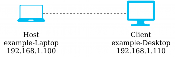
ROS Distributed Setup
Andrew from the Perception team investigated and documented this approach which significantly improves the simulation performance. This allowed us to better validate our algorithms, and exclude the possibilities that our designs are underperforming due to computational bottleneck.
RViz Visualisation
Here, we provide some simulation results from RViz, which is a powerful visualisation tool that works well with ROS. The car starts by driving slowly through an exploratory lap where it maps out this unknown race track. After that, it completes 3 at a higher speed of 8-10 m/s.
- Cylindrical markers represent the traffic cone detected by LiDAR sensor. These are coloured to reflect the type of traffic cone detected.
- Spherical markers represent the map that SLAM has constructed, which builds up over time.
- Green path in front of the car is generated by the path planner, which geometrically determines the best path forward given the cone positions provided by SLAM.
- Yellow arrow in front of the car illustrates the point which the pure-pursuit controller is attempting to follow.
Older footage of the car been simulated in the same track is shown below. Note that in this one video, the car travels rather slowly and there are some glitches that have since been fixed.
Simulation Limitations
However, there are still some limitations that required workarounds to be implemented. Firstly, while LiDAR point cloud can be simulated in Gazebo simulator, the returning laser beam intensity is not simulated. This meant that we could not realistically simulate the cone classification part of the LiDAR pipeline which requires LiDAR intensity to operate. The workaround solution was to extract ground with information from the simulator itself and feed that into the algorithm.
Secondly, the stereo camera pipeline does not work as well as it does in real life. This is somewhat as expected as there is a pretty significant domain shift between the simulation input data and real-life input data.
At the moment, most of the full integration testing is conducted with LiDAR only.
Next Steps
The next milestone, which is centered more around the control and optimisation sub-team is the fast lap path-planner and path-follower. So that the car can leverage the complete map information and attempt to complete the remaining laps as fast as possible.
About the Author:
 Steven Lee
Spatial & Perception Engineer, 2020