MUR Blog - 2018 Aerodynamics and ANSYS CFD
The design of an effective aerodynamics package is by no means an easy task. Designers must consider many aspects of the elusive subject of fluid dynamics. ANSYS allows the Melbourne University Racing Aerodynamics team to use Computational Fluid Dynamics (CFD) to simulate how different design geometries affect various aspects of race car performance; downforce, lift and drag.
The Melbourne University Racing aerodynamics team uses the ANSYS Fluent CFD package extensively during design, to optimize our package consisting of front wing, rear wing, undertray, nosecone & side-pods. An effective aero package ultimately helps improve the cars performance around the track. ANSYS Fluent allows us to simulate the car in various straight-line and cornering conditions, while measuring three critical parameters – downforce, drag and mass-flow rate. The goal of the aero team is to design for maximum downforce, minimum drag and to provide adequate airflow to the radiators for effective cooling.
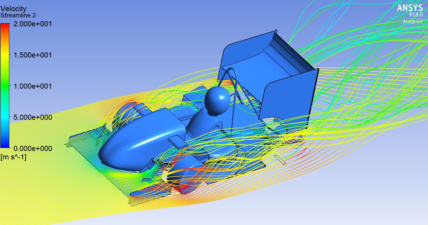
Figure 1: Straight-line simulation
The first step in running a virtual wind tunnel simulation through ANSYS is fashioning a wind tunnel in ANSYS’ built in CAD software. MUR employ both straight and curved wind tunnels during simulation to ensure the car is simulated across a variety of conditions (Straights, Yaw & Cornering) to maximise the robustness of the overall package. Once the appropriate tunnel is generated, the CAD model of the car is introduced to the wind tunnel and the complex geometry is then abstracted into millions of smaller tetrahedral elements. The mesh is then inspected and refined in ANSYS’ meshing environment, to ensure the abstraction of the geometry is as faithful to the original model as possible. The setup is then initialised with the appropriate specifications (known as boundary conditions), which define the mechanics within the virtual wind tunnel, and the simulation is initiated using ANSYS’ solver “Fluent”.

Figure 2: Cross-Section of Refined Rear Wing Mesh
Once the simulation is completed, the team digest the generated drag and lift values for both the model and its constituent components and integrate these with the interactive visual information afforded to us by ANSYS’ post-processing tool. This affords the team an intuition of what geometric adjustments can be made for further aerodynamic improvement.
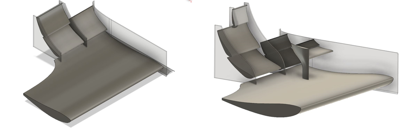
Figure 3: Geometric adjustments based on ANSYS simulations made to the 2017 Front Wing (left), resulting in a higher-performance 2018 Front Wing (right)
Apart from maintaining similar downforce performance as the 2017 design due to 20mm ride height increase, the 2018 front wing is focused on flow management for the other aerodynamic components. The inner portion of the wing coupled with nosecone wing directs the air right into rear wing. The cascades along with outer portion of the wing creates an out-wash around and over the front tyres to reduce the turbulent flow generated by the rotating tyres, which then goes back into the radiator, increasing the mass flow rate and hence improving the cooling performance.
Another important use of Fluent is the measurement of mass flow rate to the radiators, which is required for the cooling sub-teams. The radiator is simulated as its own separate wind tunnel, which allows us to measure the mass flow rate of air through it. The aero team then relays the mass flow rate data to cooling who can dimension their radiator to have the necessary surface area to deliver optimal cooling, while optimising for radiator mass. Adequate and consistent cooling is extremely important for the engine sub-team, to ensure optimal engine performance on track.
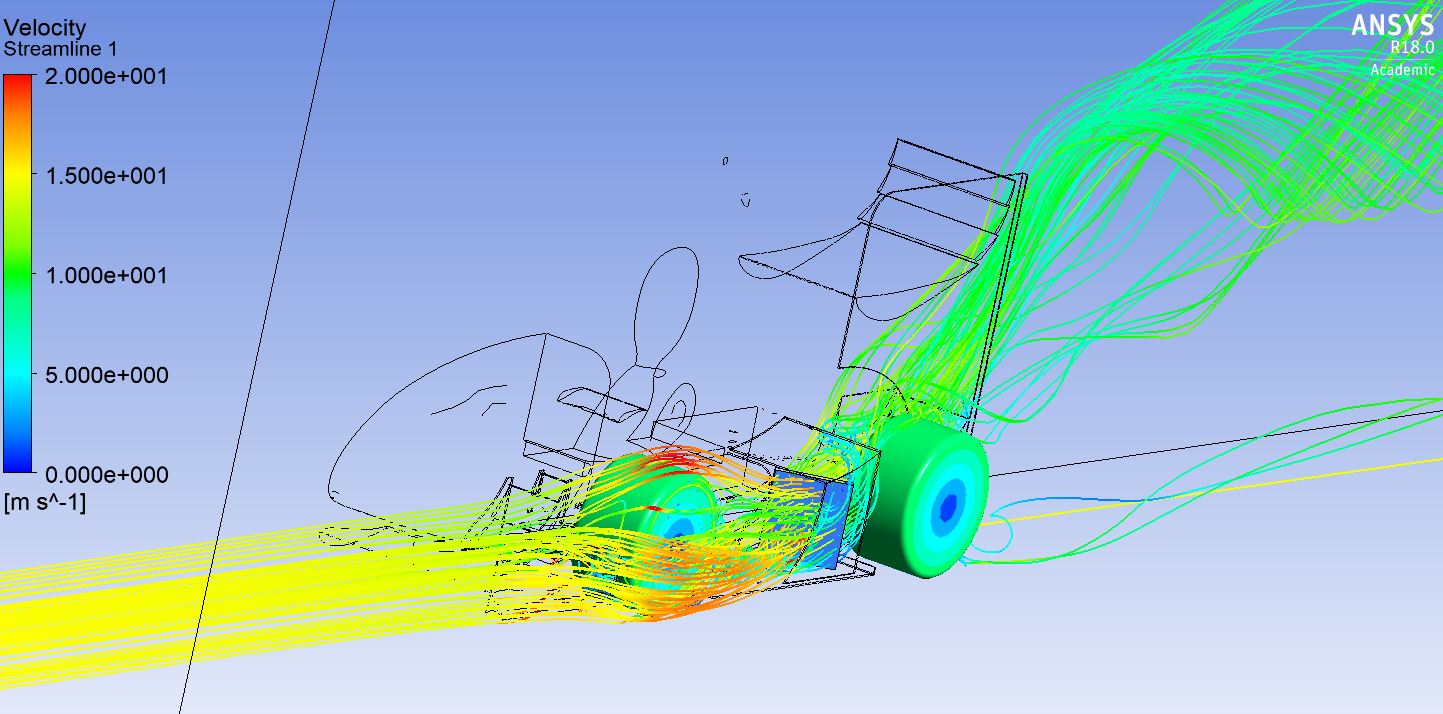
Figure 4: Simulating Airflow to the Radiators for Cooling Optimisation
The design and optimisation of our high-performance aerodynamics package would not be possible without assistance from our partners at ANSYS.
Authors:


Jarrad Haywood, James Karabatsos, Wilson Zheng
Aerodynamics, 2018